[Enter the name of the output file.]
.DIMENSIONS (NX,NY): 64,64
[Enter the dimensions of the image in the output file.]
[Following pattern menu appears.]
MENU:
| B | BLANK, CONSTANT DENSITY |
| C | CIRCLE |
| G | GAUSSIAN CIRCLE/ELLIPSE |
| G1 | 1ST ORDER GAUSSIAN CIRCLE/ELLIPSE (0...1) |
| G2 | 2ND ORDER GAUSSIAN CIRCLE/ELLIPSE (0...1) |
| G3 | 3RD ORDER GAUSSIAN CIRCLE/ELLIPSE (0...1) |
| R | RANDOM DENSITY PATTERN |
| S | SINE WAVES |
| T | TWO SINE WAVES |
| W | DIAGONAL DENSITY WEDGE |
.OPTION (B/C/G/G1/G2/G3/R/S/T/W): T
[Enter the desired pattern option.]
.DENSITY: 12.0
[Enter the desired intensity for the image.]
.RADIUS (FLOATING POINT): 12.0
[Enter the desired radius of the circle. Any floating point number between 0.0 and SQRT[(NX/2)**2 + (NY/2)**2] may be specified.]
[The output file will then contain a circle of specified radius
filled with pixel values of 1.0, and a blank (pixel value 0.0)
background. Circle will be placed at SPIDER image center.]
.CENTER COORDINATES X,Y (OR <CR> FOR IMAGE CENTER): 12, 23.12
.CHARACTARISTIC RADII IN X & Y: 4, 2
[Enter the radii for Gaussian function this is approximately the
radius at which the value is half height.
A 2D Gaussian density distribution is created. The normalization
is such that the sum of all the pixel densities is equal to one.
Note that such normalization is not usefull in creating
a mask. Use 'G1,G2,G3' for typical mask creation.
'G2' and 'G3' are super-Gaussian masks of order 2 and 3 with squared or cubed Gaussian falloffs and are generally better than 'G1' for most uses. Their densities are in the form:
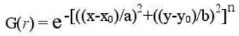
where n is the order of Super-Gaussian, and a and b are the semi-principal axes of the ellipse.
.CENTER COORDINATES X & Y (or <CR> FOR IMAGE CENTER): 12, 23.12
.CHARACTARISTIC RADII IN X & Y: 4, 2
[Enter the radii (same as standard deviations) for Gaussian
function. Controls radius of mask.]
.GAUSSIAN DISTRIBUTED? (Y/N): N
[For 'N' a random image with values uniformly distributed between 0 and 1 is generated. If 'Y' is specified, SPIDER will ask:]
.MEAN AND STANDARD DEVIATION OF GAUSSIAN DIST.: 0.0, 0.35
[Enter the mean value and standard deviation of the Gaussian
distribution for random numbers to be generated.]
.NUMBER OF SINE WAVES: 2
[Enter the number of sine waves to be added together. The maximum is 20.]
.I=1 AMPLITUDE, PHASE, SP. FREQUENCY (KX,KY): 1.0,45.,1,10
[Enter the amplitude and phase of the first sine wave,
and its X and Y frequencies, respectively.]
.I=2 AMPLITUDE, PHASE, SP. FREQUENCY (KX,KY): 2.5,90., -2,5
[Enter the relative amplitude and phase of the second
sine wave, and its X and Y frequencies, respectively.]
[The output file will now contain an image of the specified size, which is the sum of two sine waves, of specified amplitudes and phases, one of X-frequency 1 and Y-frequency 10, and the other of X-frequency -2 and Y-frequency 5. Note that the amplitudes and phases must be given as floating point numbers.]