CTF FIND - Contrast Transfer Function - Estimation of CTF parameters

(11/5/15)

PURPOSE

Estimate defocus, astigmatism and astigmatism angle for the CTF. This operation is normally used on a large original micrograph since it can create and average multiple 2-D power spectra windowed from the micrograph. Uses CTFFIND3 developed by Nikolaus Grigorieff at the MRC Laboratory of Molecular Biology in Cambridge. CTFFIND3 is licensed under the terms of the GNU Public License version 3 (GPLv3).
Here CTFFIND3 has been modified to output a SPIDER format power spectrum, and to output defocus and astigmatism using SPIDER conventions to SPIDER operation line registers and to a line in a doc file. Note: CTFFIND3 may hang if given a image size that is a prime number! Further info on the CTF related operations in SPIDER.   Example.

SEE ALSO

RO SD [Rotational average - single line output, doc file]

USAGE

.OPERATION: CTF FIND [def],[ang],[mag], [dfmid1],[dfmid2], [mrcang]
[This operation can return six optional register variables:
Variable Example Receives
First [def] defocus
Second [ang] SPIDER astigmatism angle
Third [mag] SPIDER astigmatism magnitude
Fourth [dfmid1] MRC defocus along "long" axis
Fifth [dfmid2] MRC defocus along "short" axis
Sixth [mrcang] MRC astigmatism angle

.INPUT IMAGE: mic0001
[Enter name of the input image.]

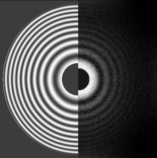
.DIAGNOSTIC POWER SPECTRUM FILE: diag_pow0001
[Enter name for the diagnostic power spectrum image. This image can be used to check the result of the fitting. It shows the filtered average power spectrum of the input image in one half, and the fitted CTF (squared) in the other half. The two halves should agree well for a successfull fit. Example output.]

.SPIDER POWER SPECTRUM FILE: pow0001
[Enter name for the SPIDER format power spectrum image. This is an average power spectrum over the whole active area of the micrograph. This image can be used for rotational averaging.]

.OUTPUT DEFOCUS DOCUMENT FILE: defocus-by-micr
[Enter name for document file which will contain 8 register columns of defocus and astigmatism information.]

.KEY FOR DEFOCUS DOCUMENT FILE: 1
[Enter key/image number for output document file.]

.SPHERICAL ABBERATION CS [mm], VOLTAGE [kV], & ACR: 2.0, 200, 0.10
[Enter spherical aberration coefficient of the objective (in mm), electron beam voltage (in kV), and amount of amplitude contrast (fraction). For ice images this may be about 0.07, for negative stain about 0.15.]

.MAGNIFICATION, PIXEL SIZE [um], & BOX SIZE [pixels]: 50000, 14, 500
[Enter magnification of original image, pixel size on scanner/camera (in um) , and box size to be used (in pixels). Box size must be even number. The operation windows tihe input image into square tiles and calculates the average power spectrum of the tiles. Tiles with a significantly higher or lower variance are excluded; these are parts of the image which are unlikely to contain useful information (beam edge, film number, etc)]

.LOWER & UPPER RESOLUTION [A]: 35, 7.5
[Enter resolution range in Angstroms to be fitted.]

.LOWER DEFOCUS [A], UPPER DEFOCUS [A], & DEFOCUS STEP [A]: 10000, 40000, 5000
[Enter defocus range in Angstroms to be searched and the defocus step (in Angstroms). Positive values represent an underfocus. The program performs a systematic grid search of defocus values and astigmatism before fitting a CTF to matching precision.]

NOTES

  1. Reference: JA Mindell, and N. Grigorieff. 2003. Accurate determination of local defocus and specimen tilt in electron microscopy. J. Struct. Biol. 142:334-47

  2. Output document file produced by this operation contains 8 register columns:
    1. Micrograph number
    2. Defocus (average of long and short axis defoci)
    3. Astigmatism angle
    4. Astigmatism magnitude
    5. MRC defocus along "long" axis
    6. MRC defocus along "short" axis
    7. MRC astigmatism angle (counterclockwise angle between x axis and long axis defocus)
    8. MRC astigmatism magnitude

  3. In MRC and CTFFIND3 output the angle and magnitude of astigmatism are represented differently than in SPIDER. Astigmatic angle is measured from X axis (same convention as in the MRC 2D image processing programs). The CTFFIND3 values are converted to SPIDER's convention using:
    Spider_defocus = Average of defocus along long and short axes
    Spider_astig = Difference of defocus along long and short axes
    Spider_angle_astig = MRC angle of astigmatism - 45;
    If (Spider_astig < 0) Then:
       Spider_astig = -Spider_astig
       Spider_angle_astig = Spider_angle_astig + 90

  4. CTFFIND3 may hang if given an image size that is a prime number!

  5. From Niko Grigorieff: 'Normally the pixel size of the scanner can be found in the manual. It is either given as the actual size (for example 7 um, as for the Zeiss SCAI scanner), or it is given as dots per inch (dpi, for example 4000 dpi for the Nikon Super Coolscan 9000 ED, which equals 6.35 um per pixel). If you do not know the pixel size of your scanner you will have to calibrate it with an image that contains features of known spatial spacings or lengths. For example, you could scan an image of a ruler and count the pixels per mm and work out the pixel size that way.'

  6. Typical K2 camera pixel size: 5um and for Falcon camera: 14um.

SUBROUTINES

CTFFIND3

CALLER

UTIL4